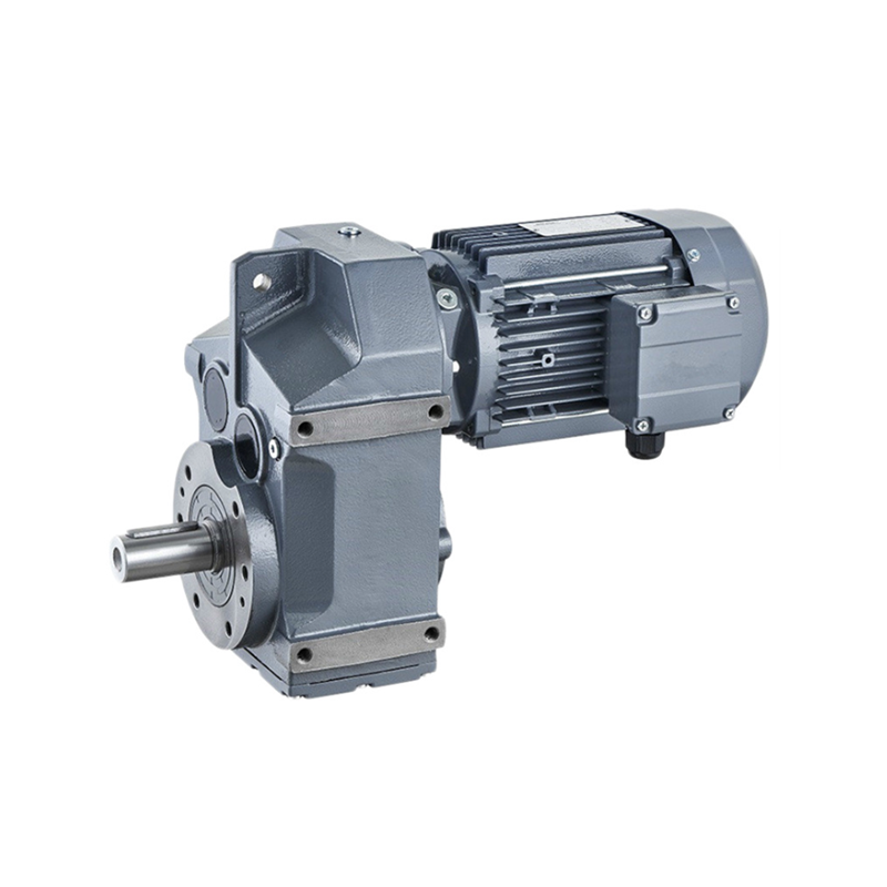
Observing a handful of guidelines for accurate installation is essential towards the reliable and appropriate operation of the gearbox or gear motor.
The guidelines set out listed here are intended like a preliminary guidebook to choosing gearbox or gear motor. For successful and appropriate set up, follow the guidelines offered while in the installation, use the maintenances guide for that gearbox offered from our sales department.
Following is a brief outline of installation principles:
a) Fastening:
Place gearbox on a surface offering adequate rigidity. Mating surfaces should be machined and flat.
Mating surfaces should be within definite geometric tolerances (see manual). This is specially true of flange-mounted gearboxes with splined hollow shafts.
In applications that involve large radial loads on the output end, flange mounting is recommended for some gearbox sizes as this mounting tends to make use of the double pilot diameters provided in these gearboxes.
Ensure the gearbox is appropriate for the needed mounting place.
Use screws of resistance class eight.8 and above to safe the gearbox. Torque up screws for the figures
indicated from the related tables.
With transmitted output torque better than or equal 70% from the indicated M2max torque, and with
frequent movement reversals, use screws with minimum resistance 10.9.
Some gearbox sizes could be fastened making use of both screws or pins. Of pin seated inside the frame the gearboxes be no less than one.five instances pin diameter.
b) Connections
Secure the connection parts to gearbox input and output. Will not tap them with hammers or related equipment.
To insert these components, use the services screws and threaded holes presented within the shafts. Be sure you clean off any grease or protects through the shafts before fitting any connection 
Fitting hydraulic motors.
Be cautious the O ring among motor flange and gearbox input flange when assembling. Install the
hydraulic motor just before filling lube oil in to the gearbox.
Connecting the hydraulic brake.
The hydraulic circuit ought to be such to make sure that brake is launched instants prior to gearbox starts and applied right after gearbox has stopped. Examine that stress from the hydraulic line for brake release is at zero anytime gearbox is stopped.
Course of rotation
Motors are linked for the appropriate electrical or hydraulic circuit in accordance with their path of rotation.
When executing these connections, keep in mind that all gearboxes, no matter whether while in the in-line or correct angle design, possess the similar direction of rotation each at input and output. For more specifics from the connection of electric and hydraulic motors, see appropriate sections within this catalogue.
motor
TAGs:
